The front custom subframe has had a few minor design tweaks since it was first built and required a general cleanup. I went over the subframe and cleaned up any sharp edges, hammering out any minor dents, then re-did a few messy welds.
The thin steel at the rear of the front subframe is fine for a Mini engine however I wanted to strengthen it for the Toyota Starlet turbo engine which has almost three times the power of the Mini engine it's replacing. To ensure parts didn't warp during welding, I fitted the subframe and rolled the Mini shell on its side to get better access to the subframe/floorpan.
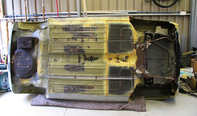
Some additional 1.6mm steel pieces were tacked in place on the subframe :
Both sides completed and welded in (there is already a 3mm steel plate joining the two subframe sides) :
The front upper suspension arms need to be removed to replace the rubber seals on either end of the arm, service/replace the needle bearings or simply make it easier to change the suspension rubber cone/trumpet from within the subframe tower. The factory Mini the upper arms are easily removed by first pulling out the pivot shaft from within the upper arm then removing the arm :

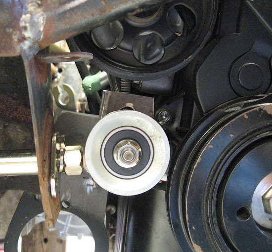
Unfortunately with many Mini engine swaps including this Toyota Starlet 4E-FTE, the engine is so wide that the pivot shaft cannot be removed as the engine and gearbox block its' removal. This photo shows the shaft is blocked by the pulleys on the drivers side (The nut on the pivot shaft has not been tightened in this photo) :
My solution was to modify the subframe to allow the pivot shaft to also be removed rearward. The subframe normally has a 1/2" hole on the rear of the subframe towers for part of the shaft to seat into :

I made a custom locking plate that will replace this 1/2" mount hole.
The 1/2" hole on the rear side of the subframe tower was enlarged, with mount holes drilled to match the custom locking plate.
The pivot shaft remains fitted in the same position however this new setup allows me to remove the pivot shaft through this enlarged hole.
A 1/4" nut was also TIG welded to the inside of the tower for one of the locking plate bolts as this nut would not be accessible once the upper suspension arm is fitted. In this photo you can just see a factory-welded 1/4" nut welded inside the tower on left hand side.

To remove the pivot shaft rearward it required a opening in the upper footwell to access the locking plate bolts and pull the pivot shaft into the cabin footwell area. The drivers footwell (wheel arch adjacent to the opening) :
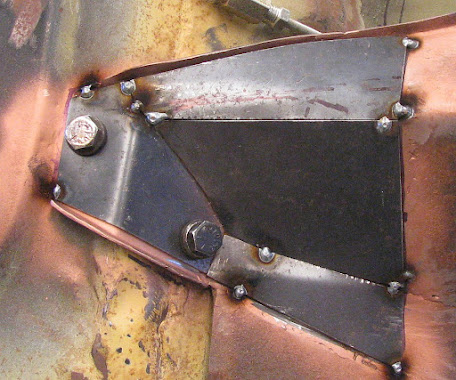
Blanking plates (to be sealed with a custom rubber/neoprene gasket) were then made to close out the opening. The small bump in the plates also provides some additional clearance to the large nut of the end of the pivot shaft.

On the shell exterior I welded/formed a perimeter and nuts.
Drivers side plate fitted. I chose to use studs at the top of the plates as there is very little clearance on the exterior side of the footwell panel (once the subframe is fitted) for a nut/bolt arrangement.

I've also seen some high powered classic Minis form cracks in the toe board (front floor pan) due to the forces and movement of the engine/subframe back and forth. To mitigate this I welded on some 2mm spreader plates onto the floorpan, where the subframe bolts through.

In the factory Minis you need to pull back the carpet to access these and undo these nuts, however I welded them to the plates.


Comments
Post a Comment