Continuing on items in the engine bay...
The intake manifold has always had a serious clearance issue where it fouled with the master cylinder brake line, and one of the manifold runners was only 3mm from the bulkhead.
Since the master cylinder cannot be moved, I chose to cut away some sections from the manifold for clearance. 

I made some patch pieces and had a local guy weld the supplied aluminium pieces on, and also weld the idle valve mount back on to the end of the manifold. 
Despite how substantial the modification looks, only ~2mm of the inside of the inlet manifold runner is blocked.


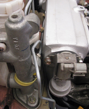
I needed to mount my Turbosmart Boost-tee manual boost controller and route two lines to the turbo and wastegate actuator. With everything fitted in the engine bay, there is extremely limited space available in front of, or on the left hand side of the engine for the controller and lines so I mounted it to the side of the head.


Two custom hard lines were then made, TIG welded to a supporting bracket and bolted to the engine lift point. I contacted the Turbosmart technical support team and they advised that the Boost-Tee will be fine to handle the heat in that setup, however recommended the use of high temperature silicone hose for the connections instead of rubber.

The Boost-Tee ends up being tucked in behind the intake piping, while remaining easily accessible for adjustment of boost levels if required.


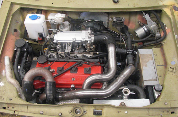
All custom engine bay parts were now completed, however to confirm I had not missed anything I started to fit every single part into the engine bay (engine, radiator, intercooler, wiring, plumbing, brackets, cables, all accessories) and check for issues. I found a couple of things to resolve :
When I first made the coolant hard line under the intake manifold (to join the heater core outlet to the water pump suction pipe) I had not considered clearance to the subframe. The hard line did actually foul on the subframe and I pulled the engine out to remake it.
The old hard line touching the subframe :


A new hardline was made to clear the subframe and battery ground terminal :

Some time ago I had moved the radiator position and trimmed part of the airbox intake duct for clearance. I had always planned to remake the duct as it ended up warped with a non-symmetrical shape.

This time I designed and 3D printed a duct that bolted to the side of the airbox, into captured nuts in the duct flange.


The duct is adjacent to the radiator so like all other 3D printed items for the Mini, I will be reprinting the piece in PETG plastic which has a higher temperature rating than PLA.

The drivers side brake line had to be remade so it now squeezes in-between the subframe tower and the engine mount.

I needed a simple mount on top of gearbox for the front bumper section of wiring loom :

...and a mount for the diagnostics connector (Non ODB-compliant for the 1992 engine)


Another issue was the intake piping that slightly squashed the distributor wiring loom.

This was solved by adding a small bend in the pipe to raise it slightly.

One final minor item was to fix the frayed end of the accelerator cable that was previously shortened. This was fixed with a quick touch from the TIG welder, then cleaned up on the bench grinder.


The engine bay layout is now 100% complete.

Comments
Post a Comment