With most of the wiring layout already sorted, I had a couple of items to complete in the cabin - starting with the heater control assembly.
I've already fabricated the custom heater control assembly for the dash but I needed a way to route the power from the cabin wiring loom to the fan power switch and speed controller (top left in the photo below). I decided on a simple circuit board which I designed and had fabricated via pcbgogo.com. The PCB also includes a power supply to a T-10 wedge globe for a backlight through the heater lever slot.
The wiring loom for the combination switches (lights, indicators, wiper stalks behind the steering wheel) in the Toyota Starlet is secured to the underside of the steering column and is hidden by the dash. In the Mini however, this section of the column is exposed and wiring is quite visible.
I removed the original mounting tabs from the steering column and fitted a wiring loom mount under the custom steering column mount which will hide the wiring loom above the column.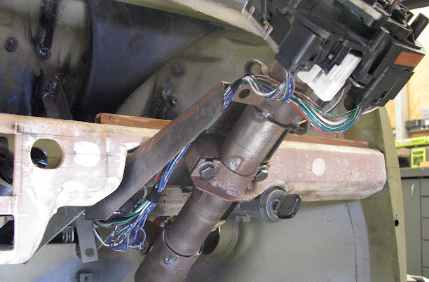
It was then time to wrap the main sections of the cabin wiring loom. I covered most of it in split loom tube then wrapped everything in Tesa cloth/fleece loom tape. Some bare ends have been left unwrapped and will be cut to the correct length and fitted with appropriate connectors during the final install.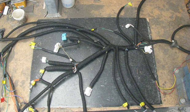
I also welded in a section of curved steel tube where the rear loom routes up under the rear seat to allow the loom to sit flatter without rubbing on the hole. The rear seat will be unused so there's no risk of the loom getting crushed.
The floor cross-member had some 21mm tubes welded in to make it easier to feed the wiring through.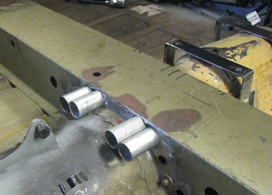
The wiring that will be routed through these four tubes are :
- Rear wiring loom - handbrake, rear lights, indicators, fuel pump & level, boot light, reverse camera
- Power, ground, lighting signal to digital display & wideband controllers
- Sensor wiring for digital display
- Wideband oxygen sensor wiring (6 wires just for this sensor) 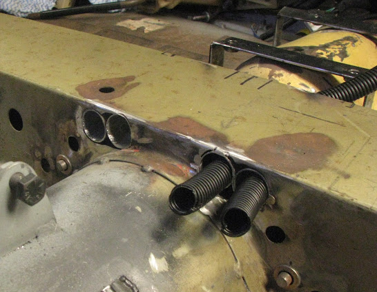
The cabin loom was installed to confirm fitment was okay post-wrap, and it's certainly a squeeze behind the Mini dash! This will eventually need a bit of a tidy up with cable ties during the final install.
I found that there was not enough room under the gear shifter to fit the rear wiring loom, power/sensor wiring for the digital display controller & wideband controller (controllers are mounted under the drivers seat) and so had to remake the gear shifter mounts slightly higher to provide additional space.
Old mount (using retrofitted Toyota Starlet factory mounts) :
The central locking actuator and power window motor wiring in the doors needed some mounts welded on to secure the wiring looms.
The Mini never had any wiring in the doors from factory and with only a 7mm gap in the door jamb, there was literally no room to use a normal rubber loom tube in the jamb so I decided on routing the wiring over the door check strap - similar to what's used in the JK Jeep Wrangler.
I first had to make new check strap pieces & mounting pieces, as I did not have the original ones :
The cabin loom wiring will end at a couple of connectors just below the dash, and the door wiring will be another separate loom so if the doors ever need to be removed, then it's as easy as disconnecting a couple of connectors under the dash, then unbolting the doors.
A cover piece to hide the wiring was made using an open end zip and this was then sewn to the new check strap made from 50mm seat belt webbing. This allows me to conceal the wiring and also easily remove it in the case of any repairs :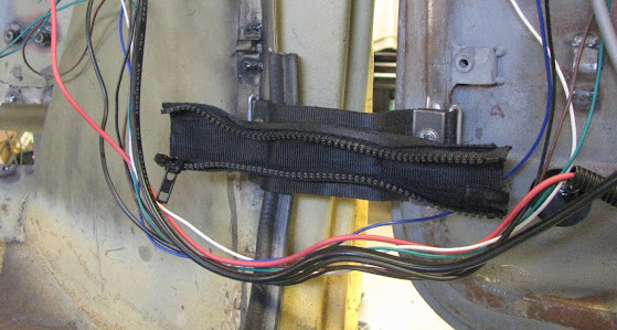


Comments
Post a Comment